Drill and tapping unit
About This Project
The assignment of my graduate internship was to design and build a special machine that was able to drill and form metric thread on the faces of metal rods. These rods are a key component in most conveyor rollers.
The most important specifications were as follows:
- Axle materials: Carbon steel, stainless steel 300 and 400 series
- Axle length from 100 [mm] to 2500 [mm]
- Axle diameter from Ø6 [mm] to Ø35 [mm]
- Threads from M4 to M16
- Maximum changeover time 10 minutes
The design started with concept sketches, making exploratory calculations as we went along. We spent most of our time designing the fixation and positioning component, this would determine how accurate our machine was going to be. All of the concepts were either fast interchangeable but had a high risk of positioning errors, or they were more stable but therefore took more time to swap out. Then we started to combine our concepts and came up with the following idea:
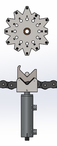
The hydraulic cylinder pushes the axle against a fixated “disk” with multiple cutouts, one for each rod diameter. This disk is mounted on a axle and secured by a removable pin. This combined a fast interchangeable setting with high rigidity to minimize positioning errors.
After further implementing this idea into the sub-frame the design looked something like this: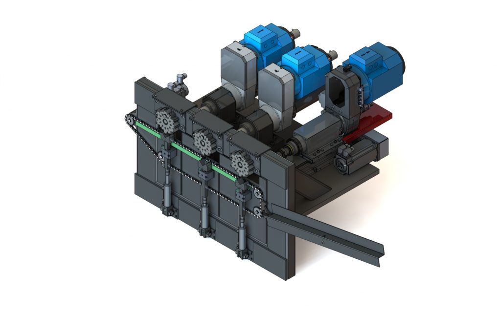
To check the strength calculations, a FEM analysis has been made:
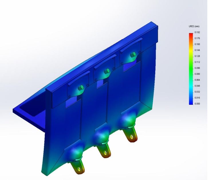
This ofcourse gives an extremely exaggerated visualization, looking at the legend the max displacement is around 0,2 [mm]. This displacement is caused by the force the hydraulic cilinders exert on the frame, and because of the fact that this force is the same every time the positioning error is the same as well. Therefore this error can be canceled out by mechanical adjustments in the fixation of the “disk”.
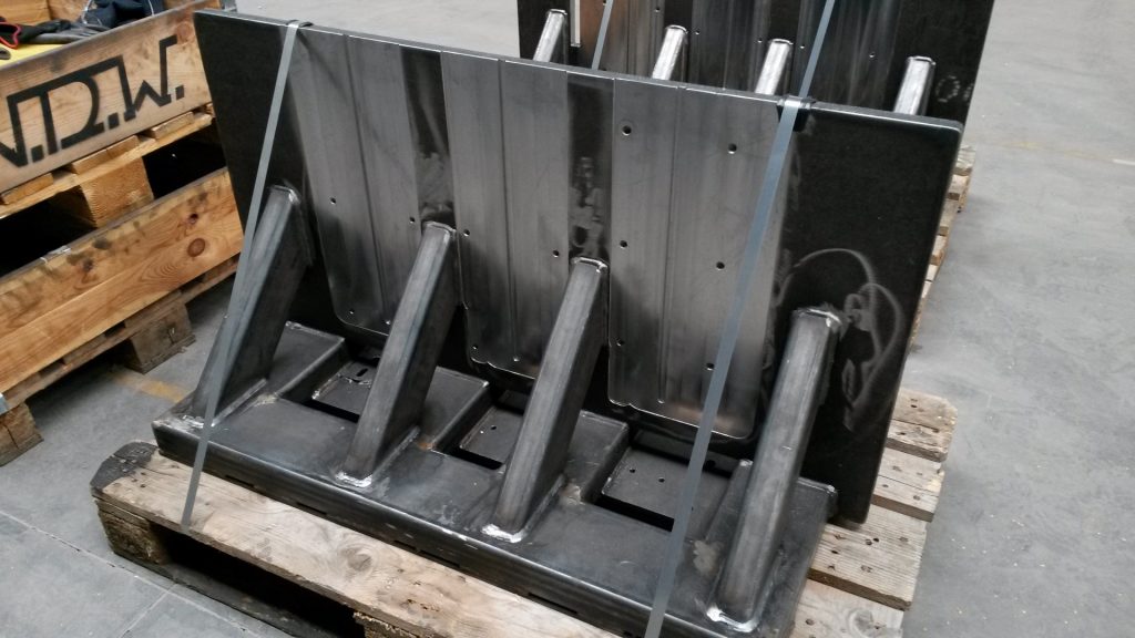
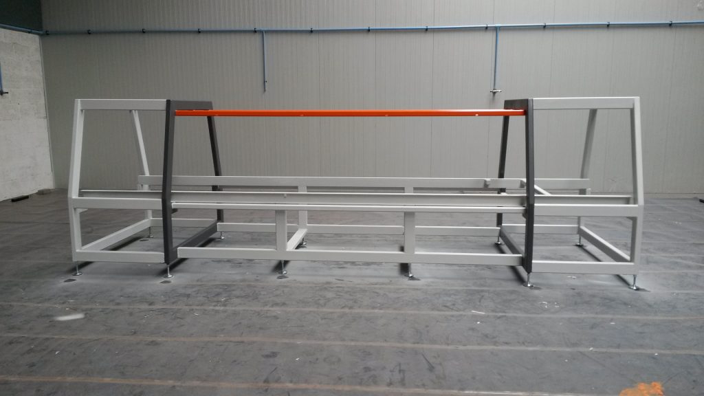
After creating the 2d drawings the realization began, starting with cutting and welding the frame and sub-frames:
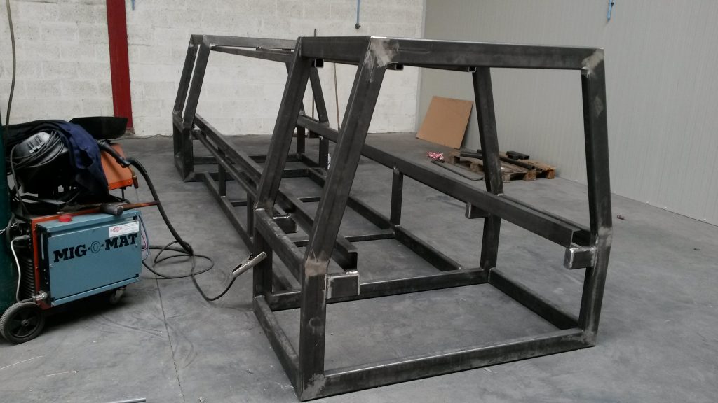
Welding of the sub-frames: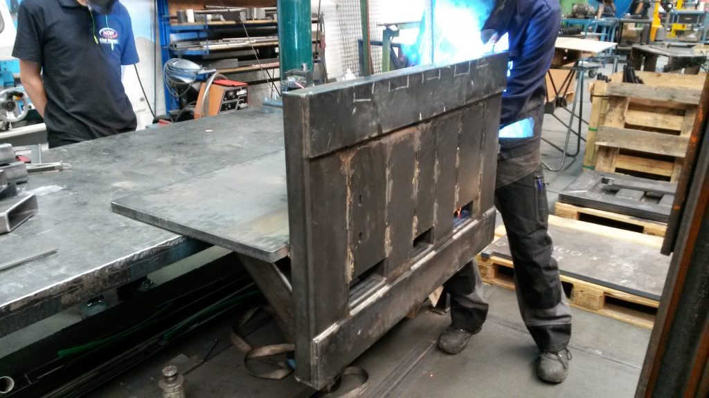
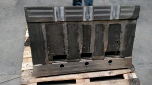
The material tends to bend as result of the heat generated by the welding process. To make sure all the relevant surfaces were flat and level the frames were machined:
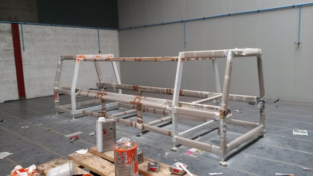
Painting of the frame:
Next up, mounting the sub-frames with the milling units:
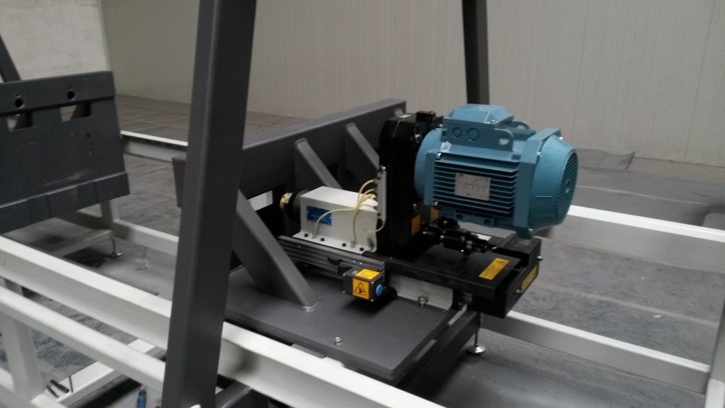
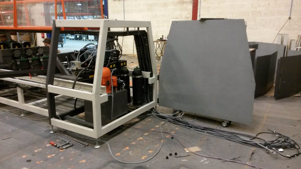
First view of bare machine with protection:
After all components were placed, hydraulics, pneumatic and electric wiring were done:
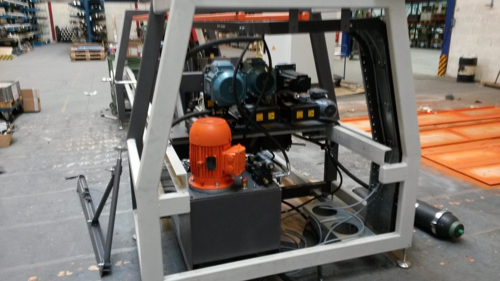
The Hydraulics were outsourced to a company near NDW that specializes in these units. I have installed and commissioned the system. All electronics and PLC software were outsourced, although the wiring itself was done by me. I managed all the outsourced projects, form quotations up until completion.
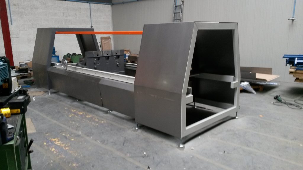
And the finished result!
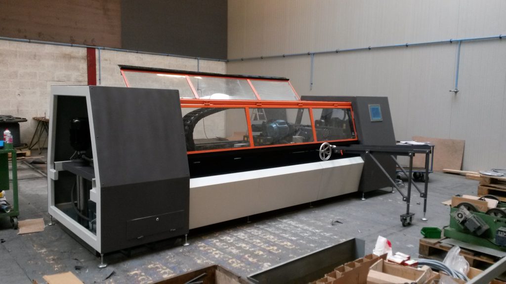
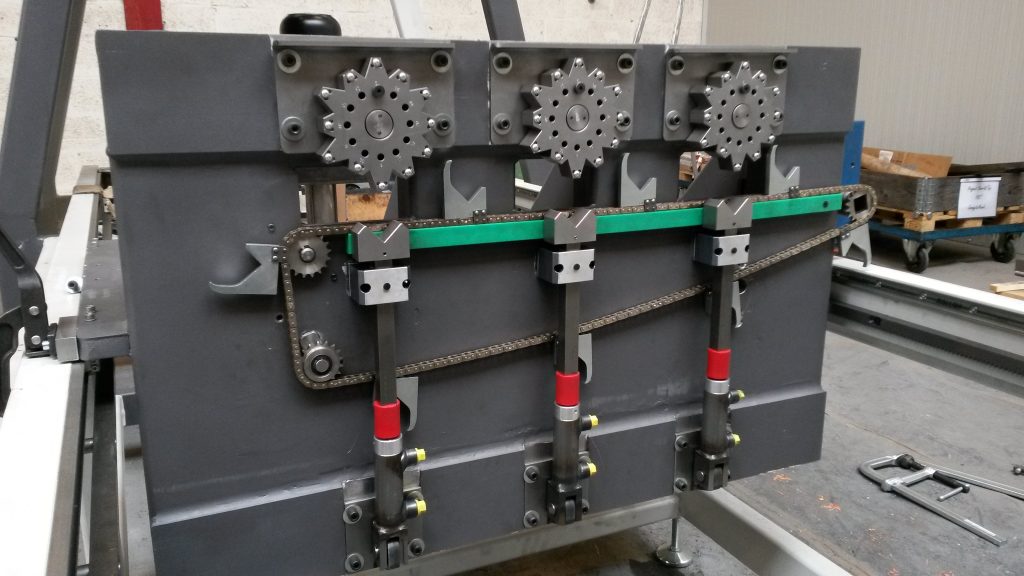
The machine recently had a major revision of which this is the result:
The “disk” which positions the axles is being changed with round cutouts instead of straight ones. This ensures a better fixation because of the larger contact patch with the axle. As a result of this the hydraulic pressure can be lowered which reduces the chances of the fixation being pressed out of alignment. Also, because of the fact that the axle how centers itself in the round cutout, I have made the hydraulic cylinder assembly flexible to position itself straight under the axle. The cylinder assembly is now free to move a couple millimeters to the left and right. With this design, the cylinder never presses at an angle due to alignment errors.
Aside from the fixation we started experimenting with thread forming. With this process no chips are being made and the thread is much stronger then with thread cutting. The taps themselves are much more rigid, so especially with smaller sizes (M4, M5 and M6) the tap does not break as quickly.
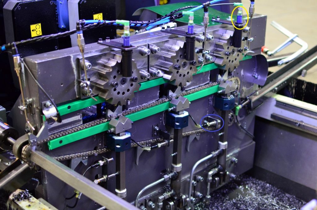
Furthermore, the machine detected if there was a rod in one of the machining stations by inductive sensors, marked with blue. These activated when the cylinder could go all the way up, meaning there was no rod in that station. Because this sensor had to detect rods as small as 6 [mm], the alignment came fairly precise. With the new free floating cylinder assembly, this method of detecting a rod was not reliable enough.
To overcome this problem I have mounted and programmed three sonic sensors (marked yellow), these emit an ultra high frequency sound that reflect on the rod if one is present. The sensor uses this reflection to determine if there is a rod in that specific position. The main advantage of these sensors is that they do not give a false positive when a metal chip comes near. The black tube was added to focus the sound and to ensure no coolant gets on the detection surface of the sensor. These sensors work with a standard NO/NC contact, and were therefore not too difficult to program in the PLC software.